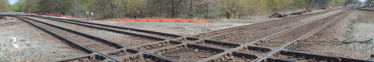
It is past time to put some numbers to the problem of building an HSR line over clay. In summary, Leda clay is a very poor medium on which to build HSR tracks, with damaging vibrations induced at speeds as low as 172 km/h (48 m/s), although with significant engineering effort, by strengthening the soil to a depth of around 4 metres under the entire railway, the low-frequency vibrations can be sufficiently reduced to the point where at speeds of 270 km/h to 300 km/h, track degradation and sonic shockwaves become nuisances rather than severe physical constraints on operating the railway.
Regardless, deep deposits of Leda clay should be avoided in HSR construction where possible, in particular between Ottawa and Hawkesbury, where alignments north of the Ottawa River may be preferred.
Engineering properties
To calculate the displacement and strain in soil under the railroad, I’m using the stiffness matrix method by Eduardo Kausel. This provides an analytic solution for soil that is uniform in the horizontal and layered in the vertical under the assumptions of linear soil response. That linearity assumption means the calculation is only valid while the strain remains small and the soil undamaged. Measurements by Abdellaziz et al. show this to be true for strains up to between 0.01% and 0.015%.
While sound in a homogeneous medium will travel at a mostly uniform speed of sound, in layered media, some of the wavefronts can pass through neighbouring layers at a different speed, creating a strong dependency on the sound speed with the frequency of the wave. The stiffness matrix calculates the pressure at a layer boundary when given an applied displacement as a function of frequency and wavelength. To get the sound speed in the layered systems, one finds the ratio of the wavelength vs. frequency at which the displacement blows up for an applied pressure; this is the inverse of the stiffness matrix, called the flexibility matrix. Kausel defines a critical speed whenever the sound speed reaches a local minimum as a function of frequency1.
To construct these matrices, the elastic parameters of the soil are then needed, preferably in the parameterization of primary and secondary speeds of sound, density, and damping coefficients.
For many soils, and in particular clay, these elastic parameters change with the overburden pressure, and thus depth, of the soil layer. I will adopt two sets of parameters. The first, for St-Étienne-de-Beauharnois clay from Abdellaziz et al. (2021) as they seem somewhat representative of clays found through most of the basin. A profile of somewhat weaker clay was found at the South Gloucester site near Ottawa.
Table of soil parameters at Beauharnois
| Layer | Depth from original soil surface (m) | Layer density (kg/m³) | Secondary/shear speed of sound (m/s) | Primary/compressive speed of sound (m/s) |
| Ballast and sub-ballast | -0.2–0.4 | 1100 | 197 | 300 |
| Dewatered clay crust | 0.4–1 | 1850 | 100 | 163 |
| Beauharnois clay | 1–6 | 1620 | 75 | 1500 |
| 6–8 | 1640 | 79 | 1500 | |
| 8–9 | 1690 | 83 | 1500 | |
| 9–10 | 1750 | 89 | 1500 | |
| 10–12 | 1800 | 95 | 1500 | |
| 12–14 | 1850 | 100 | 1500 | |
| 14–18 | 1900 | 104 | 1500 | |
| >18 | 1940 | 110 | 1500 |
Notes:
- The thickness of the clay crust is set to a fairly shallow 1 m for this study but can vary depending on local conditions, in particular drainage.
- The parameters for the ballast and sub-ballast are set following Fernandez-Ruiz, Castanheira-Pinto, Costa, and Connolly (2022).
Table of soil parameters at South Glouscester
| Layer | Depth from original soil surface (m) | Layer density (kg/m³) | Secondary/shear speed of sound (m/s) | Primary/compressive speed of sound (m/s) |
| Ballast and sub-ballast | -0.2–0.4 | 1100 | 197 | 300 |
| Dewatered clay crust | 0.4–1 | 1400 | 120 | 200 |
| South Gloucester clay | 1–3 | 1670 | 75 | 1500 |
| 3–5 | 1570 | 60 | 1500 | |
| 5–8 | 1700 | 79 | 1500 | |
| 8–10 | 1550 | 79 | 1500 | |
| 10–12 | 1550 | 95 | 1500 | |
| 12–15 | 1580 | 120 | 1500 | |
| 15–18 | 1710 | 135 | 1500 | |
| >18 | 2000 | 170 | 1500 |
Critical speed over thick clay
On top of these soil layers, layers with stiffness and moduli equivalent to steel rail and under-rail pads may be added. For UIC 60 profile rail, this gives an equivalent steel plate thickness of 5.95 cm.2 The under-rail pads are assumed to provide 50 MN/m of stiffness at every 0.67 metres along the rail.
As a function of frequency, zeros of the real value of the stiffness matrix were calculated for the soil conditions at Beauharnois with UIC60 rail overlaid.
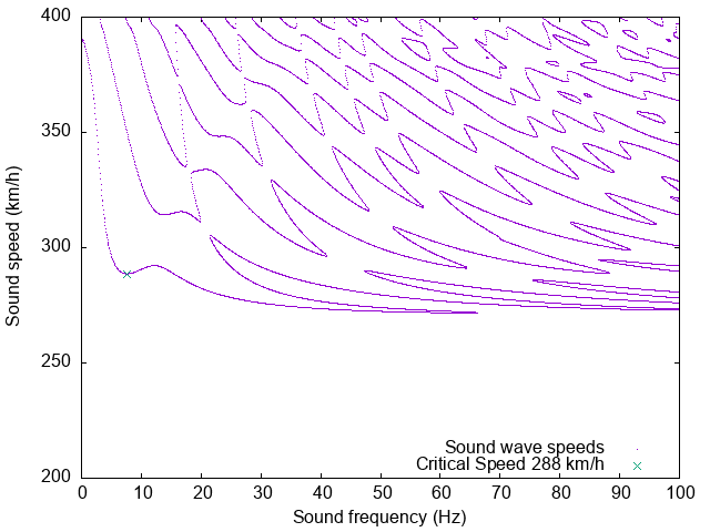
This plot provides the surface wave sound speed for all the modes in the simulated soil, including those that are significantly damped. The strongest mode is the one generated by the first minimum, around 288 km/h, Kausel’s critical speed for this simulated soil. At higher frequencies, some weaker modes propagate in the slowest layer of the soil, in this case at 75 m/s or 270 km/h.
When looking at the soil at Gloucester with UIC60 rail,
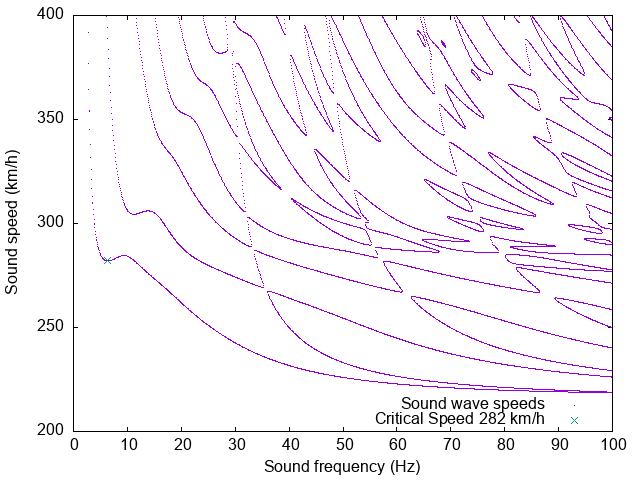
the critical speed is slightly less than that for the soil at Beauharnois, but the effect of the slowest layer in the soil (at 60 m/s or 216 km/h), at 3 to 5 metres in depth, is noticeable at higher sound propagation frequencies.
The full effect is that one should expect the ground, and thus the track, to shake and distort as one approaches these critical speeds of around 280 km/h assuming the soil behaves linearly as in these models.
Displacement of the railbed
To understand the displacement of the rail under a train, the soil stiffness matrix must be multiplied by the source of vibration from the train’s moving weight applied to the rail. For this, a solution in one dimension with repeating boundary conditions was implemented. The source was an infinitely long HSR train with bogies alternately spaced every 17.4 metres and 8.4 metres apart and 2.5 metres between the axles on each bogie, and a 15-tonne axle load per bogie. This is close to the loading one would see from a Siemens Velaro trainset. The weight of the train is assumed to be spread over the 2.59 metre width of a typical rail tie. Finally, the displacement and strains are measured in just the x and z directions. At shallow depths under the rail, the acceleration and displacement calculated should be a slight overestimate of the actual acceleration and displacement.
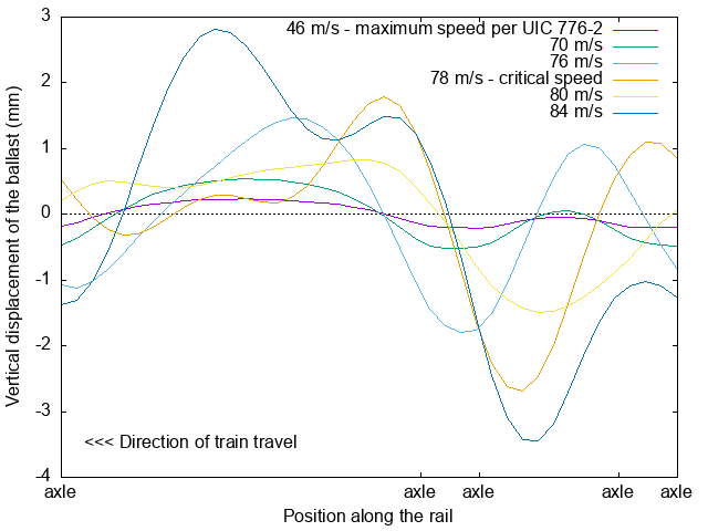
For the South Gloucester soil model, the vertical displacement of the ballast under the train is shown above. When approaching the critical velocity, a sharp shock just ahead of the axles forms. From these displacements, the acceleration of the base of the ballast can be calculated, where the UIC 776-2 limit of 0.35 m/s² for this acceleration is reached at a speed of only 48 m/s or 172 km/h. Above this speed, with a safety margin, the ballast will shake sufficiently so as to reduce its hold on the track structure.
Shear in the subsoil
The stiffness matrix method relies on the soil having a linear response under load.iI.e., the soil is assumed not to weaken. For Leda clay, this is a reasonable assumption until shear strains exceed about 0.000,15. Above that level, the bonds in the clay start to break, and the speed of sound in the soil is reduced.
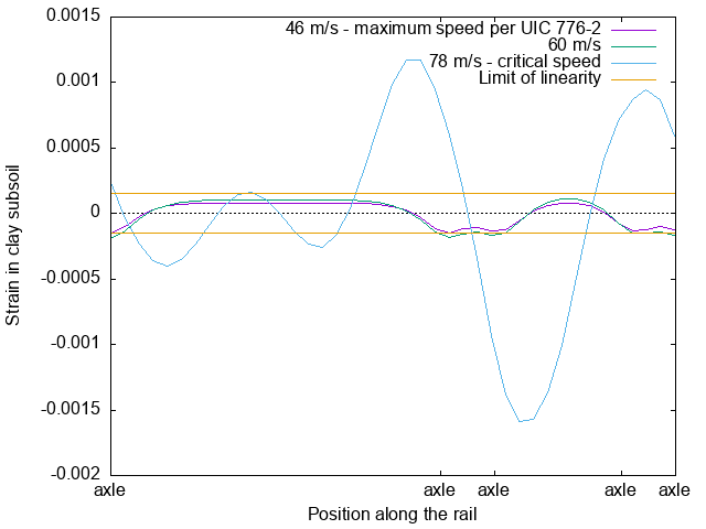
Even at low speed on a ballasted track, and assuming a dry clay crust in the first metre of soil, this linearity limit is nearly exceeded. With higher speed operation, the limit is exceeded, and the critical speed can be assumed to reduce. Upon approaching the critical speed, the soil would start liquifying the soil under the passage of a train, not necessarily at the 78 m/s calculated above.
Leda clay in the presence of strengthened soil layers
Since running HSR on thick layers of Leda clay is problematic, what if there is only a thin layer of clay over shallow bedrock?
This strengthening could occur at depth in the soil. For instance, if HSR is running over a shallow bed of clay, say 1 metre of clay crust over 1 metre of soft clay laying over bedrock, the overall stiffness of the soil and the critical speed increase. However, this increase is relatively modest. For the Beauharnois soil model, the UIC 776-2 vibration limits and soil linearity limits are reached at the following speeds, only just exceeding 200 km/h for shallow 2m clay deposits.
| Bedrock depth (m) | Limiting speed due to vibration (m/s) | Limiting speed to maintain shear < 1.5e-4 (m/s) |
| 2 | 62 | 96 |
| 3 | 60 | 82 |
| 4 | 54 | 70 |
| 5 | 52 | 64 |
| 6 | 52 | 62 |
| 8 | 50 | 56 |
| 10 | 48 | 54 |
| infinite | 48 | 54 |
Stiffening the soil layers on top of clay deposits is somewhat more promising. These allow the load of a train to be spread over a significantly larger surface of the weak clay.
One simple expedient is to use track supported on a concrete slab. Using the model of Ruiz et al. for the stiffness and thickness of a slab supported track over thick Beauharnois clay, the critical speed is increased to 331 km/h, vibration can be kept below 0.35 m/s² at 60 m/s (216 km/h), and excessive soil shear avoided up to 80 m/s (288 km/h). On this type of track, given no need to maintain ballast stability, the vibration limits might also be relaxed assuming the slab is sufficiently resilient. Keeping acceleration below 1 m/s², a speed of 78 m/s (280 km/h) may be possible, albeit with potentially disruptive sound shocks being transmitted to neighbouring properties.
Strengthening of the soil by introducing cement can also help. Assuming ballasted track over clay strengthened by addition of cement to a shear modulus of 100 MPa, strengthening the soil to a depth of 2 metres increases the speed at which vibration exceeds 0.35 m/s² up to 64 m/s (230 km/h) and the soil shear limit isn’t exceeded until 90 m/s (324 km/h). With 3 metres of strengthened clay, the vibration limit is at 74 m/s (274 km/h) and with 4 metres of strengthened clay, the limit is reached at 86 m/s (310 km/h). At 4m and greater depths, the speed limit is likely underestimated given the 1-dimensional loading model being used.
A reminder of two caveats. Firstly, in these models, the shear strength of the soil needs to be improved to spread the live load. Simply transferring the load to lower strata with piling is insufficient, especially as Leda clay provides very poor anchoring to piles. Secondly, this calculation provides limits to ensure the track remains acceptably undamaged. Acoustic shocks may still propagate through soil layers with low speeds of sound, especially if they encounter structures such as foundations coupled directly to that soil layer.
In certain areas, in particular near Trois-Rivières, there are strata of sand or other firm soils overlaying clay deposits. The shear dynamics of sand are somewhat complicated, but sufficiently thick layers provide support similar to or exceeding that of cement strengthened soil analyzed above. Thus, sand layers of 4 metres of depth or more should be able to support HSR trains at 300 km/h over thick beds of clay without causing track damaging vibrations. Sand is also a better attenuator of high-frequency sound waves that would still generate acoustic shocks in any clay at depths less than 10 m.
Outcome and caveats
It’s useful to go back to the map generated two posts previous to this one, now with the Prescott and Russell trail added, to see where the speed of high-speed rail would have to interact with clay deposits.
Note that the blue areas shown on this map indicate that the clay is at a deep layer in the soil, but does not indicate whether higher layers in the soil are suitable for rail construction. Many of the areas shown with deep clay east of Ottawa are overlaid with bog.
In approaching Ottawa from the east, laying rail on clay will be unavoidable, but the extent to which rail is laid on sensitive clay may be minimized. In particular, rail alignments that cross the Ottawa river either near Orleans or near Thurso may permit 300 km/h operation in closer proximity to Ottawa than other alignments could.
On the Montréal-Quebec segment, this analysis also suggests that certain corridors should be preferably be avoided. In particular, the A-40 alignment just east of Trois-Rivière, which runs over clay where the existing rail corridor largely avoids the worst of it, and between Terrebonne and l’Assomption, where poor soil is likely unavoidable with construction over either clay or bog.
It has been suggested that the flat terrain between Ottawa and Montréal make this the easiest segment of ALTO’s high-speed rail project to construct. When accounting for the need for high-speed on sensitive soils, this assumption doesn’t hold.
The code used to generate the data for this post are available at https://github.com/fbfree/Leda_critv.
- In signal analysis, the poles of the matrix, the zeros of the determinant in the complex number plane, would be used to define a critical point. However, Kausel’s definition is useful for finding the lowest real sound speed in proximity to a critical point. ↩︎
- The stiffness of a pair of rails in 2-dimensions vertically along its length is given as the moment of inertia of the rail, which can be converted to an equivalent box section with a width of one’s choice. This box section needs to be converted to the equivalent depth of a semi-infinite layer for use with the stiffness matrix method. Here, the assumption is taken that the load from the rail typically applied across a width of 2.59 metres, the standard length of a rail tie. Thus the layer thickness is taken as that of box section of steel with 2.59 metres of width and the equivalent stiffness of the modelled rail. This method is likely to underestimate the peak pressure on soil under a train, depending on the stiffness of the ties in use. ↩︎